The exploded diagram of the worm gear box assembly. The parts are as

Download scientific diagram | The exploded diagram of the worm gear box assembly. The parts are as follows: 1-cover; 2-bearing; 3-worm shaft; 4-cover; 5-bearing; 6-gear box body; 7-bearing; 8-oil seal; 9-cover; 10-plug; 11-worm gear rim; 12-worm gear hub; 13-output shaft; 14-bearing; 15-oil seal; 16-cover from publication: Image-assisted collision detection for calculation of an assembly interference matrix | The assembly interference matrix is a foundational information model for assembly process planning such as assembly sequence and assembly path planning, and supports digital assembly simulation, intelligent assembly, digital twin-based assembly, and so on. The assembly | Collision Detection, Assembly and Matrix | ResearchGate, the professional network for scientists.
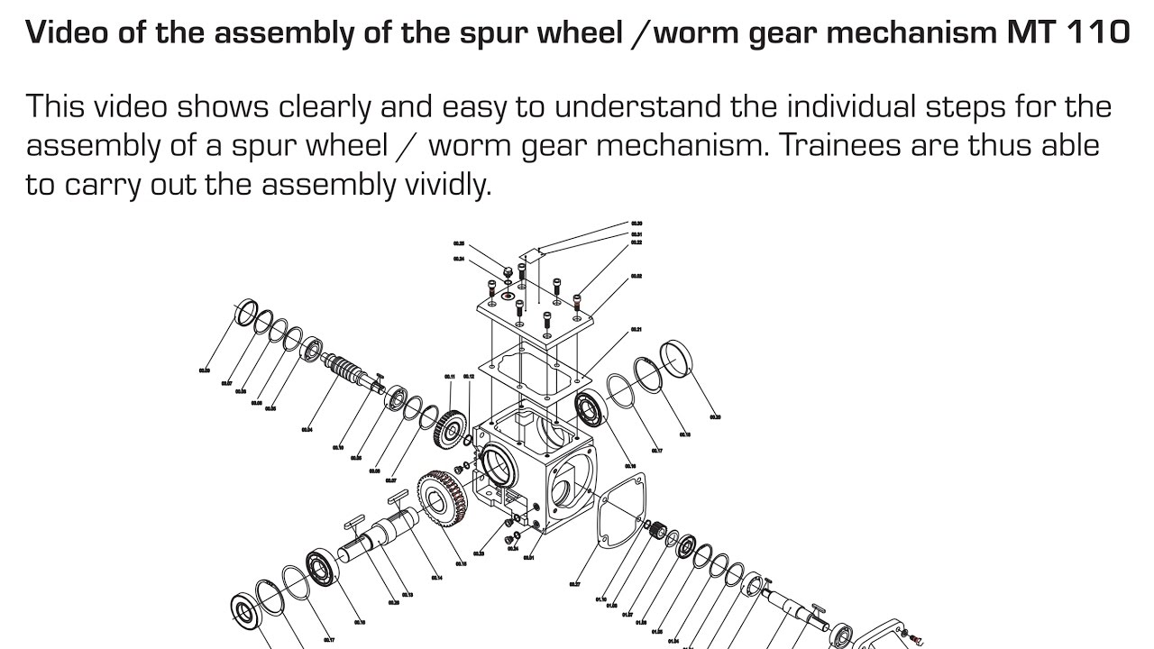
Assembly of the spur wheel /worm gear mechanism MT 110 EN
The%20LiftMaster%20K75-50224%20gate%20operator%20top%20gear%20box%20assembly%20(also%20known%20as%20part%20Q210)%20is%20compatible%20with%20select%20L

LiftMaster K75-50224 Top Gear Box Assembly
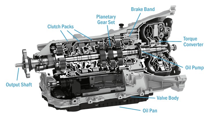
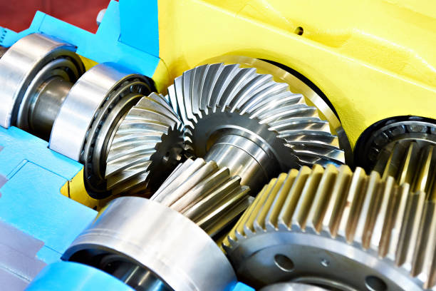
Gearbox Components and Parts: Everything You Need to Know - Industrial Manufacturing Blog
MTD 31AM66EG700 (2016) Parts Diagram for Auger Gearbox Assembly

GM Saginaw Model 800 Power Steering Box - Exploded View

Exploded Diagram Stock Illustrations – 189 Exploded Diagram Stock Illustrations, Vectors & Clipart - Dreamstime
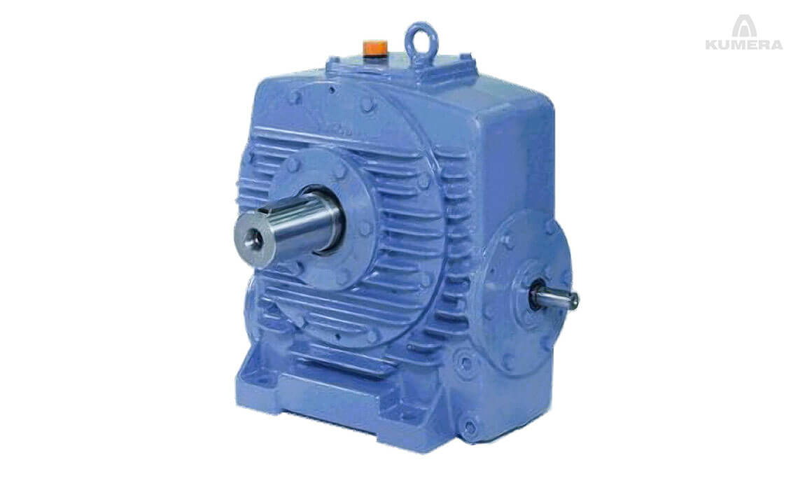
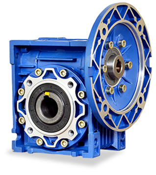
Competitive price worm gearbox has 50mm center distance, 27 Nm rated torque, 1400 rpm rated speed. The reduction ratio can be customized to 5:1/
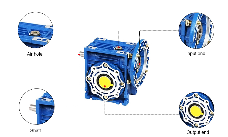
50mm Worm Gearbox, Ratio 5:1 to 100:1, 27 N.m
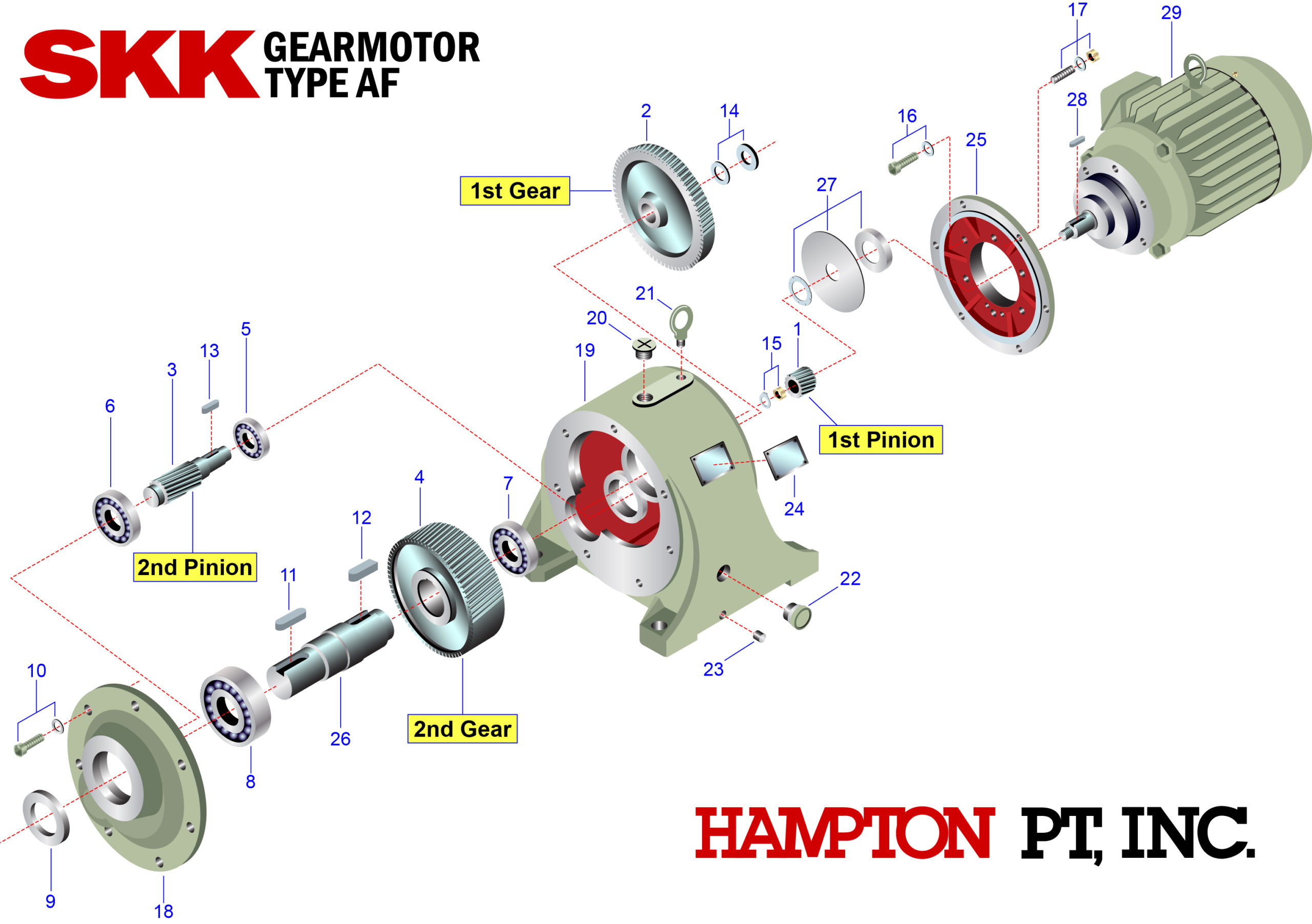
SKK Parts Breakdown - Hampton of Oregon

The exploded diagram of the worm gear box assembly. The parts are as

Gearbox - an overview

DC GEAR MOTOR/DC MOTOR Doncen Motor

FPE Models TC-525 & TC-546 Spring Drive Tear Down, Maintenance and Repair
Products